How to collimate a GSO Ritchey Chrétien telescope
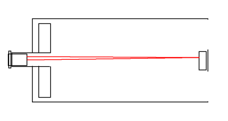
The web contains several descriptions how to collimate an RC or Ritchey–Chrétien telescope. Three methods can be identified, with a cheshire, collimation scope and using collimation laser. Note that the collimation of the primary is not recommend unless you know what your are doing.
The next try was using a collimation laser with a projection pattern as described here. Also this was a failure. The reflection back on the primary is hardly detectable even with my 635 nm laser. Secondly the projected rings pattern is not sharp. As an experiment I throw in some small paper pieces. The pattern became clearly visible but since the circle lines are at two places thicker due to the rectangle spot of laser source it is difficult to judge the projection. If both mirrors where tilted it could still produce a perfect projection pattern. So there should be at least one check fore one mirror if it is aligned with the optical axis.
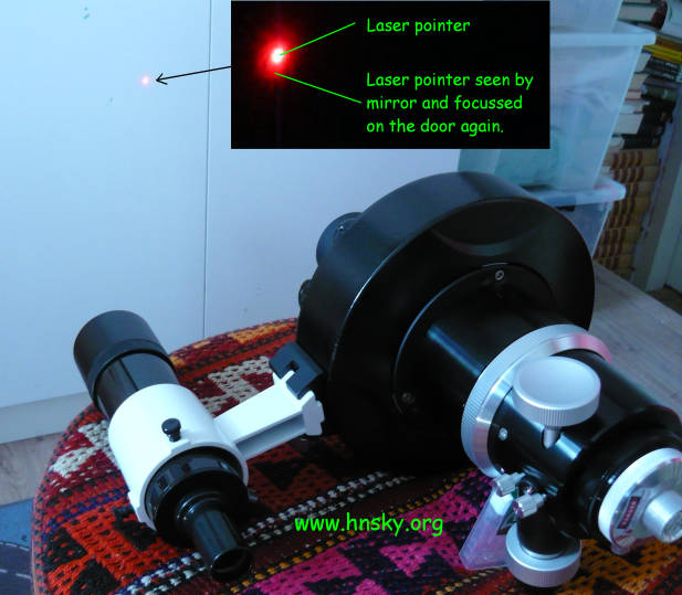
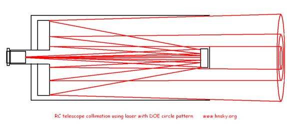
After that failure I developed the following method which can be done using a good collimation laser. Note that an RC has two adjustable mirrors. I used a collimation laser with an 1mm barlowed attachment to have a sharp laser point.
Note that looking at a 5 mw laser point could irreversible damage your eyes.
The GSO RC allows three adjustments:a) The optical axis (primary mirror) and focuser vs the tube axis (step 2). This requires normally no adjustment. Unfortunately the focus tube vs. primary mirror is not adjustable (step 1).
b) Secondary mirror collimation. This could require adjustment and normally the only adjustment you should make.(step 3)
c) Distance of secondary vs primary mirror. This requires normally no adjustment. Is however critical due the two hyperbolic mirrors (step 5)
Normally for collimation only an adjustment of the secondary mirror tilt in step 3 is required. If your not satisfied with the telescope performance, do all five steps/checks as follows:
Step 1) Primary mirror vs focuser tube: First step is to check and adjust the alignment of the focusser with the primary mirror. This is easy if the back cell is removed. In a very dark room, put a collimation laser with a sharp focus in the focuser and point it to a white flat surface. The bright spot on the white surface produced by the laser will be picked up by the mirror en if at the correct distance (a little longer then the telescope) it is focussed again as a disk around the original bright laser spot. In my case the disk by the mirror was about 5 to 6 mm off the middle indicating a not perfect squareness of the focuser versus the mirror!! By turning both the focusser and the mirror, I could found a spot where it was in the middle. Alternatively you have to install an optional adjustable tilt ring "focuser collimation" or maybe put some aluminium foil under one side of the mirror. Note that the tilt ring could block your collimation screws.
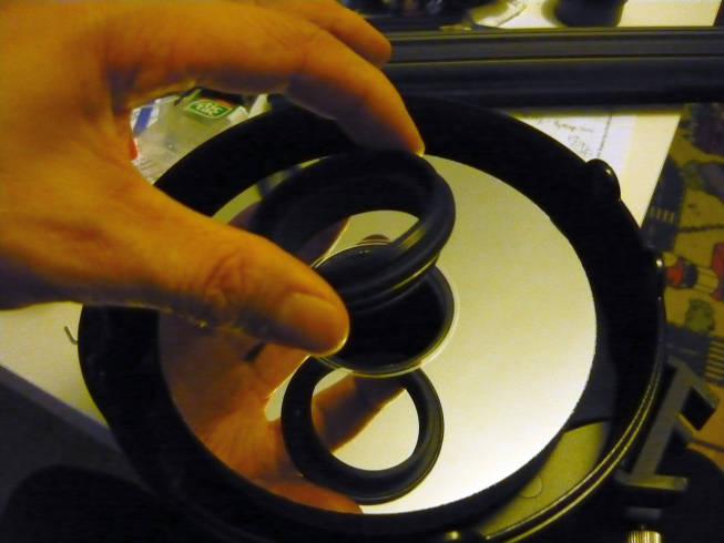
Step 2) Focuser tube and mirror vs tube axis: Put telescope in exact horizontal position and untie the three hex bolds a little and remove the secondary mirror by removing the middle screw and lay it inside the tube. It is wise the measure in advance the distance of the secundary from the spider. Due to the hyperbolic mirrors there is only one correct distance! Note the spring on the bolt between the mirror and spider mount. Be very carefully with this unmounting. It could be helpful to exercise the removal the secondary in step 1). However it should be remounted before the primary mirror cell is put back in place. With the primary mounted, the secondary mirror can't be taken out of the 6 inch telescope tube.
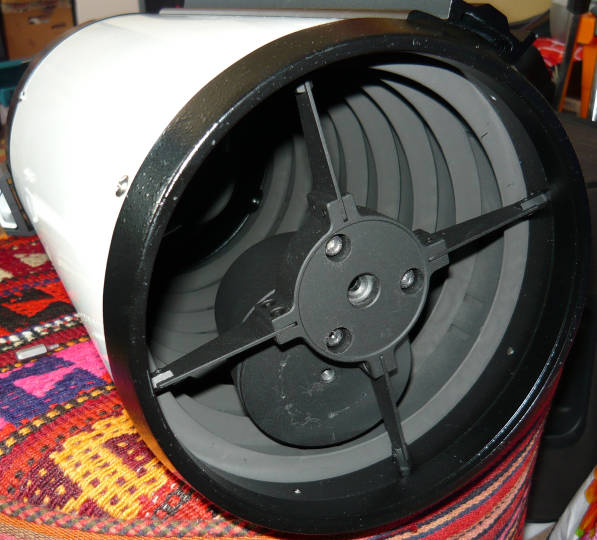
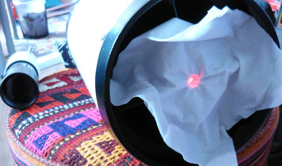
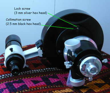
Put a tissue as a projection screen in front of the mounting hole of the secondary mirror. Place laser with a sharp pointer (barlowed with a small hole adapter) and look to the projection on the tissue and adjust primary assembly with the six bolts till the pointer is exact in the middle of the secondary mounting hole. The primary assembly can be tilted with the 6 screws. The three 2.5mm black hex head are for adjustment/collimation and the three 3 mm silver hex heads are for locking. Make only small movements of about 1/8 of a turn and compensate with the opposite screws
Never look directly at the laser pointer beam !! By aiming first the focusser tube to the secondary mirror spider, the primary is aligned directly to the optical axis assuming the focusser tube is square to the primary mirror.
Carefully remount the secondary mirror. A assume above procedure could be executed also with a cheshire. By aiming at the secondary spider mirror, the primary is aligned directly to the optical axis assuming the focusser tube is square to the primary mirror.
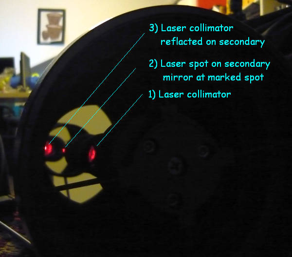
Step 3a) Secondary mirror tilt: Adjust the secondary till the point is inside the marker of the secondary. This wat you see inside the front of the telescope tube. Be sure your telescope is reasonable collimated and the bright spot is not escaping the telescope!!!
Step 3b) Secondary mirror tilt alternative method: Alternatively adjust the secondary till reflections returns exactly to the laser. This gives in my case a little different result but in my case collimation was spot on.
Step 3c) Secondary mirror tilt alternative method: This method is not better then 3A or 3b. Use the holographic attachment/diffractive optical element and adjust the secondary till the laser ring projection will show perfect rings on the wall. The reflection can been see on on the white laser disk.
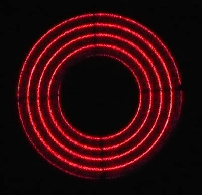
This is the pattern by the Howie Glatter collimation laser with a holographic pattern or better diffractive optical element (DOE) attachment. The center point is pretty bright and should never be looked at or leave the telescope !!. Looking inside a 5 mw laser could irreversible damage your eyes. The laser itself doesn't produces not a perfect point but more a small rectangle. That's why on two sides the circles are a little thicker.
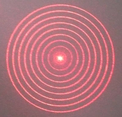
This is the projection pattern on the wall if the telescope is aligned or if the two mirrors are tilted the same amount compensating each other. In the middle the shadow of the secondary
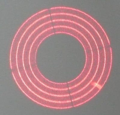
This was the wall projection of the 6 inch telescope with a laser with DOE attachment after trying to collimate the telescope traditionally using a cheshire and a artificial star only. The projection is not symmetrical:
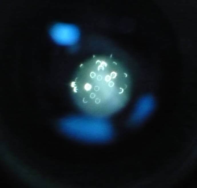
Step 4) Final collimation and check: Check at high magnification using an artificial star on 20 meter or so or on a real star visually and adjust the secondary a little if required. This artificial star could be a LED torch with a needle punctured aluminum foil in front:. Check if the out of focus stars are symmetrical.
Artificial star using a cheap torch, and second image the out of focus stars. The best punctured holes produce an out of focus ring pattern with a dot in the middle if the collimation is correct..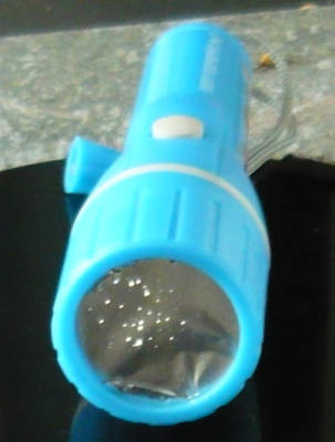
In my case after option 3b) en 3c) the collimation was almost perfect.
Step 5) Optional, distance primary secondary mirror check using astrometry:
Normally this is not required if the secondary distance is kept as found. Note that the distance can be changed by the central bolt v.s. the hex keys but also by unscrewing the secondary in its mounting and fix it again with the ring. For this type of telescopes, the spherical aberration is dependent on the distance primary to secondary, there is only one optimal distance. At the same time the focal length and backfocus (distance focal plane to tube) changes with that distance. To check the focal distance distances I used the astrometry program "Pin point Astrometry" to analyse my CCD images. From my oldest images it calculated a focal length of 1396 mm. With a flattener at a little too short distance, it calculated a value of 1379 mm. This is close to the published value of 1370 mm. So I assume it is correct to include the flattener in the focal length check. If the distance between the mirrors is increased with 2 or 3 mm, the calculated focal distance decreased from 1379 mm to 1330 mm. So a factor 10 or more as confirmed in interferometer-tests. Currently the astrometry program calculates for my setup a focal length of 1368 mm with the flattener mounted.
Flattener is required:
Without a flattener, the telescope images are only sharp in the centre. The stars in the corners of the QHY8 image look horrible comet like. It was also not symmetrical and I became suspicious about the mirror quality. However with a low cost Sky watcher /Orion Field Flattener for Short Refractors and above collimation the images are pretty good. I tried several distances between the chip and Field Flattener T-thread in steps of 7.5 mm. Best flat field is now achieved at 72 mm distance instead of the 55 mm recommended for refractors. Shorter distance gave poor results. Worst are the stars in the north-west edge of the image.
Image results:
The images are better then with my LX200. Here images of M52 en NG891 using the above field flattener at 65 mm and 72 mm distance from chip.:


The results using the well known reducer CCDT67 at 0.67, 0.75 or 0.8 ratio are all poor!! The reducer doesn't compensate for curvature and stars are not round at the corners using a 15.6 mm x 23.4 mm CCD chip/
So the 6" telescope is only usable in the F/9 configuration with a flattener for not too faint medium or small sized objects. Here all results
More info:
Note my secondary and primary mirrors of my GSO RC 6 inch where slightly loose. I carefully tied the mounting ring till it was just fixed without any stress.
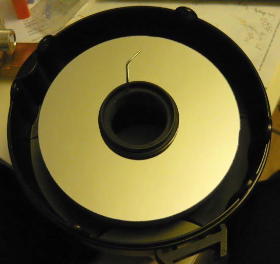
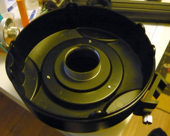
The back cell assembly:

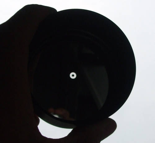
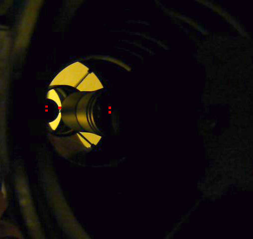
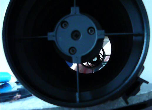
This is what some call the "hall or mirrors" after good collimation.
This is what you see at 5 meter distance. The white 1 1/4 inch soft plastic
dust cap in the focusser tube is magnified larger then the secondary
mirror.
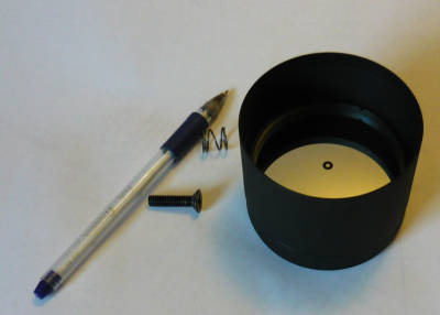
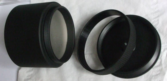
The secondary mirror can be rotated and distance could adjusted. The ring will fix the position:
The marked spot at secondary mirror is in fact a spot without reflacting
coating: